Malcolm's 3SGTE AW11

Want a thread dedicated to your car?
Got a seriously pimped-out ride? Building an extreme performance MR2? Post here!

Moderator: Moderators

Forum rules
This section of the forum is a great resource if you're looking for ideas, and it's a cool way of obtaining technical information that may otherwise not have been posted. (Members can use the Search functionality at top right of the forum to speed up finding things) Please respect others' contributions and don't diss anyone - keep comments helpful, factual, positive and polite. One thread per vehicle or owner please - don't start lots of threads about just one car. And if you need assistance with your car and want to host a spanner day, please use the appropriate section of the forum: http://mr2.org.nz/phpbb3/viewforum.php?f=35 Thank you.
User avatar
mickeyduck
Life Member - MR2OCNZ
Posts: 6144
Joined: Mon Apr 25, 2005 11:30 am
Stomping Ground: Auckland
Prime Mover: More than one MR2
First name: Charlie

Re: Malcolm's 3SGTE AW11

Post by mickeyduck »

I didn't say air flows down through the engine bay Malcolm... it does indeed flow up as you've deduced.

The reason a standard lid's vents face forwards is because the air is traveling forwards across the engine lid, and yes those vents are exhausts, not intakes.

As for the standard spoiler, it isn't even in the airflow at 100kmh as my tell-tale tests showed years back.
100kmh-wing-aero.png
100kmh-wing-aero.png (256.96 KiB) Viewed 5660 times
The way the standard spoiler (very slightly) helps decrease the drag is by assisting the vortex that is happening over the engine lid.

Air flows off the roof, but swirls down near the rear wing, flows forwards along the engine lid, and back up at the rear window. This air is reasonably slow moving and is referred to as a "separation bubble". This slow moving bubble of air acts as if the car had a gently sloping rear roof allowing the laminar layer to flow nicely rearwards, some distance above the engine lid and boot lid.

The separation bubble also helps generate higher pressure around the back of the car as compared to what there would be without it. Shear vortices are detached some distance behind the separation bubble too, thereby further reducing drag. The same thing reduces drag in a ute with its rear door up and no tray cover with an empty tray, as (not very scientifically) demonstrated by Mythbusters.

If you Google about separation bubbles and aero you'll see what I mean.

If you look at the tell-tales in my test shot you'll see the laminar flow above 15cm and the rear edge of the separation bubble is causing the tell-tales below 15cm to drop lazily down. In fact you can even see the very bottom tell-tales are being gently sucked forwards.

I once left a jersey on the engine lid and some kilometres later noticed it in my rear view mirror, snuggled up against the rear window.

Here's a separation bubble showing the direction of its flow, as featured in a scientific aero discussion:
separation_bubble.png
separation_bubble.png (134.56 KiB) Viewed 5660 times
And here's my depiction of the aero on an AW. Green is separation bubble flow (slow moving), pink is engine air flow, brown is laminar flow of the air as it hurtles past the car.
DSCF4641.JPG
Basically if you wanted to assist your aero you would vent your engine bay forwards and upwards near the rear window, and if anything fit an almost vertical spoiler on the rear edge of the boot, perhaps 15cm tall. Because my tests showed that the laminar flow misses the top of the rear edge of the boot by about 15cm at 100kmh, therefore a spoiler to that height would assist in maintaining the separation bubble.

If you leave your engine vent at the rear edge of the boot I suggest you add a near-vertical spoiler above it to prevent your engine vent from destroying the separation bubble (and thereby increasing drag).

Anyway that's my amateur 5 cents' worth Malcolm. :wink: Doubtless any number of critters may want to poo-poo my assertions on this but that's AW aero as I understand it mate.
#8^) Charlie the certified Westie
Retired - President 2012 - 2018
Retired - Committee Member 2009 - 2018
Retired - Auckland Area Coordinator 2009 - 2018
Retired - Webmaster, Forum Host & Admin 2010 - 2018 - Now it's mknz

Financial Club Member since 2004 and thanks to *84vvt and co-conspirators, Life Member since April 2017 8)
100+ MR2OCNZ runs and counting... When going hard, good rubber's your best protection against unwanted accidents. Buy good tyres!
When you're nearing the end of the drag-strip and you have no 'chute, you may as well keep your foot to the floor... Live life. There ain't no second pass. :twisted:

User avatar
Malcolm
Club Member - MR2OCNZ
Posts: 638
Joined: Mon May 24, 2010 8:24 pm
Stomping Ground: Auckland
Prime Mover: AW11
First name: Malcolm

Re: Malcolm's 3SGTE AW11

Post by Malcolm »

Interesting info Charlie. I realised that there is a circulating pocket of air above the engine lid, but interesting to know that it extends as far back as you suggest. Where did you have those telltales in the picture mounted? It's very hard to tell longitudinal position from that photo. I suspect the rear visor would help to keep the airflow attached and reduce the size of the "separation bubble" - did you have it in place for the test you did?

As I said, my experience with the small amount of aero testing I've done (on quite different vehicles) suggests that changes you make can have unexpected effects elsewhere. Simply having air exhausting from the engine bay further back on the rear deck will add some amount of energy to the airflow at the rear of the vehicle and may influence what is occurring (whether it would be to the detriment or betterment of my engine bay venting, I wouldn't want to guess!). Not only that but the airflow over the entire vehicle will be considerably affected by my bonnet vent which (should) send more air over and less under the car. Even the different mirrors on the '89 could have an influence on air flow at the rear of the car...

Anyway, this discussion has definitely piqued my interest and probably motivated me to do some wool-tuft checks on airflow on the rear sooner than I might have otherwise... Once I've got the vent laminated onto the lid I'll pop it on the vehicle and go for a quick run to see what's happening - I'm not massively concerned with small increases in drag, but I'm not that keen on choking airflow through the engine bay through a poor vent design.

User avatar
mickeyduck
Life Member - MR2OCNZ
Posts: 6144
Joined: Mon Apr 25, 2005 11:30 am
Stomping Ground: Auckland
Prime Mover: More than one MR2
First name: Charlie

Re: Malcolm's 3SGTE AW11

Post by mickeyduck »

aero-sideview.JPG
And yes the rear visor was on the car. I expect it helps both the flow of the air as well as maintaining the bubble. For that reason I'd love to make a slightly longer one that carries on at the same angle, maybe twice as wide, back to the next set of mounting screws perhaps.

I've also long considered making a perspex spoiler similar to that found on the back end of a TVR Sagaris, which I believe they found reduced drag as well as generating downforce.

Look forward to seeing your tell-tale test results! :mrgreen:
#8^) Charlie the certified Westie
Retired - President 2012 - 2018
Retired - Committee Member 2009 - 2018
Retired - Auckland Area Coordinator 2009 - 2018
Retired - Webmaster, Forum Host & Admin 2010 - 2018 - Now it's mknz

Financial Club Member since 2004 and thanks to *84vvt and co-conspirators, Life Member since April 2017 8)
100+ MR2OCNZ runs and counting... When going hard, good rubber's your best protection against unwanted accidents. Buy good tyres!
When you're nearing the end of the drag-strip and you have no 'chute, you may as well keep your foot to the floor... Live life. There ain't no second pass. :twisted:

Wayne
Guest of the Club.
Posts: 343
Joined: Sun Nov 17, 2013 12:04 pm
Stomping Ground: Manawatu
Prime Mover: SW20
First name: Wayne

Re: Malcolm's 3SGTE AW11

Post by Wayne »

I think youll find your air test on the back actually shows how the air is flowing and not a lack of it
http://bigmike.marlincrawler.com/forum/ ... topic=33.0" onclick="window.open(this.href);return false;

Yes there will be some form of a pocket , But that air still needs to return to the airflow at some point .
your test almost looks like it shows the direction of the airflow at the back of the vortes , and the rear wing may also form a splitter between the air comming from the top and the air spinning around the back of the car as well ... Its a cool test , but after having a look at this threed , You might see that you may have missed some important info :)

Hope it helps

User avatar
thelinuxwarrior
Club Member - MR2OCNZ
Posts: 152
Joined: Tue Dec 25, 2012 2:46 pm
Stomping Ground: Auckland
Prime Mover: SW20
First name: Shane

Re: Malcolm's 3SGTE AW11

Post by thelinuxwarrior »

One thing I want to do is attach Linear Potentiometers to the cars suspension. (http://www.celesco.com/linearpot/" onclick="window.open(this.href);return false;)
This would allow you to calculate the height of the car across the four corners while the car is in motion.
Assuming that you had a relatively smooth surface (hampton downs or any race track) you would be able to collect a decent measurement of the ride hight of the car
at different speeds.
If you then compare these measurements to the ride height of the car while stationary, assuming you know the spring rate of the car you could then work out,
based on the difference in ride height, how much lift/downforce the car is generating at a given speed.

I'm keen to try this out a somepoint - will it work, who knows? but should be fun either way. :-D

User avatar
thelinuxwarrior
Club Member - MR2OCNZ
Posts: 152
Joined: Tue Dec 25, 2012 2:46 pm
Stomping Ground: Auckland
Prime Mover: SW20
First name: Shane

Re: Malcolm's 3SGTE AW11

Post by thelinuxwarrior »

Double post :-(
Of course the above would only paint half a picture, you still to determine how much drag your aero mods are producing.
Determining the relative increase would be pretty easy,
Setup 2 cones / 2 points
Get the car moving at ~@200km/h
At the first cone shift to netural
Measure time taken to reach end cone and end speed.

If you do this before and after you perform an aero mod (add a spoiler) assuming initial speed is the same, you should beable to see how it compares (better or worst).
Combine this with information about downforce and then you can judge whats better: drag + downforce or less drag, less downforce.

I have been thinking about this every know and then and its something I really want to play around with on our track car :-D

User avatar
Malcolm
Club Member - MR2OCNZ
Posts: 638
Joined: Mon May 24, 2010 8:24 pm
Stomping Ground: Auckland
Prime Mover: AW11
First name: Malcolm

Re: Malcolm's 3SGTE AW11

Post by Malcolm »

We use shock pots quite a bit at work for suspension development and they useful things for sure. What you're suggesting would probably work, however you may struggle a bit with the signal to noise ratio - you might be dealing with aerodynamic lift/downforce values of the order of 10-50kg @ 100km/h, which given a spring rate of perhaps 6-15kg/mm on each axle would mean that best case you might be looking for a change of 10mm or so. Even on a seemingly smooth surface I wouldn't be surprised to see suspension movement due to road irregularities close to that figure which could make it very difficult to see the effects of any changes. Going faster should increase the ratio of movement due to aerodynamic loads to inputs from the road, but I'm not sure if it would be enough.

I don't mean to sound as if I'm trying to discourage you, but it's something to think about. Having said that - once you've acquired 4 linear pots, fitted them to the car and connected them to a data acquisition system capable of logging them at a reasonable frequency, you might find there's more gains to be had using the data to tune your dampers (if they're adjustable) rather than playing with aero :wink:

I've also done a bit of coast-down testing for measuring relative changes in drag. It's very easy and effective and you don't even need to mark out the road. Best bet is to use GPS or a good digital speed signal and coast down from 100km/h until about 5km/h. It's best done on a still day and you need to do both directions to negate the effect of any wind, but after 3 repeats each way you should have a good enough data set to have good confidence in your results. There's a road just out of Thames called Canal Rd West that I used to do this on at my old job. It's dead straight, flat and quiet so good for doing this sort of testing. There's enough driveways etc to give good landmarks for making sure you start your test at the same spot every time.

User avatar
thelinuxwarrior
Club Member - MR2OCNZ
Posts: 152
Joined: Tue Dec 25, 2012 2:46 pm
Stomping Ground: Auckland
Prime Mover: SW20
First name: Shane

Re: Malcolm's 3SGTE AW11

Post by thelinuxwarrior »

You raise some decent points for me to explore,
My hoping was that if the surface was uniform enought so that the noise was relatively constant then comparing two runs (one without mods and one with) I might be able
to determine that average difference between the two, even given the amound of noise.
The big assumption being that the noise between the two tests is the same so should beable to eliminate it. Although your right that if the noise is too great I might beable to say there is a difference,but not beable to determine the difference which kinda defeats the purpose. Edit: Assumption - The amount of noise is constant at a given speed which depends on the road surface.
You are right in that there is alot of room for inaccuracies to occur :(

Collecting the data at a decent rate won't be an issue, but what remains black magic for me is all the suspenision settings. You have given me something to think about around datalogging for tuning dampers. :-D
I'm a little way away from buying the needed sensors (im a poor uni student :twisted: ), but most of the required hardward for datalogging should be going into the car shortly. Im stealing your idea of using a hall effect sensor for speed lol after the car ate 2 nylon gears off the sender and given that the speedo only goes to 180km/h. Plan to hook this up to a tablet and replace the dash cluster. Given time when I finally get the megasquirt installed this would all talk to eachother.
Planning to have arduino(s) connected to a raspberry pi in the car for datalogging and given time and money, will slowly add sensors to it. (G sensor, shock pots etc)
Waiting for the Arduino Tre to come out which should make things easier.
Would be neat to have a complete datalogging soluction in place - what im really wanting to do is quantify any changes we make to the car.

User avatar
Malcolm
Club Member - MR2OCNZ
Posts: 638
Joined: Mon May 24, 2010 8:24 pm
Stomping Ground: Auckland
Prime Mover: AW11
First name: Malcolm

Re: Malcolm's 3SGTE AW11

Post by Malcolm »

It might be worth looking in to using rotary pots (e.g. TPS) rather than linear pots. The cost of 4x 250mm travel linear pots will be pretty significant! The other thing to check out is the resolution of the A/D conversion on the analogue channels - an Uno has 10 bit resolution so with (e.g.) 250mm of travel you'll only get 0.25mm resolution...which I suppose would be suitable for what you want to do; possibly a bit borderline if you did want to look into damper speed histograms for tuning... Anyway it sounds like it would be fun, I've been very keen to have a play with a Raspberry Pi or Beagleboard or similar but don't really have the time, or really the knowledge to do anything useful at the moment. Luckily for me an ADL3 is easily borrowable if I wanted to do any data logging on my car :)


Anyway, onto the mini-update. Thanks to Colin sending up a spare sunvisor, I got my warrant on Friday. Only thing I needed to fix was to replace the horn button on my steering wheel - it had been falling out so I put some dots of superglue on it... unfortunately the superglue seeped into the button and stopped it from working! Drove it around a little bit and was reminded of how much fun it is :)

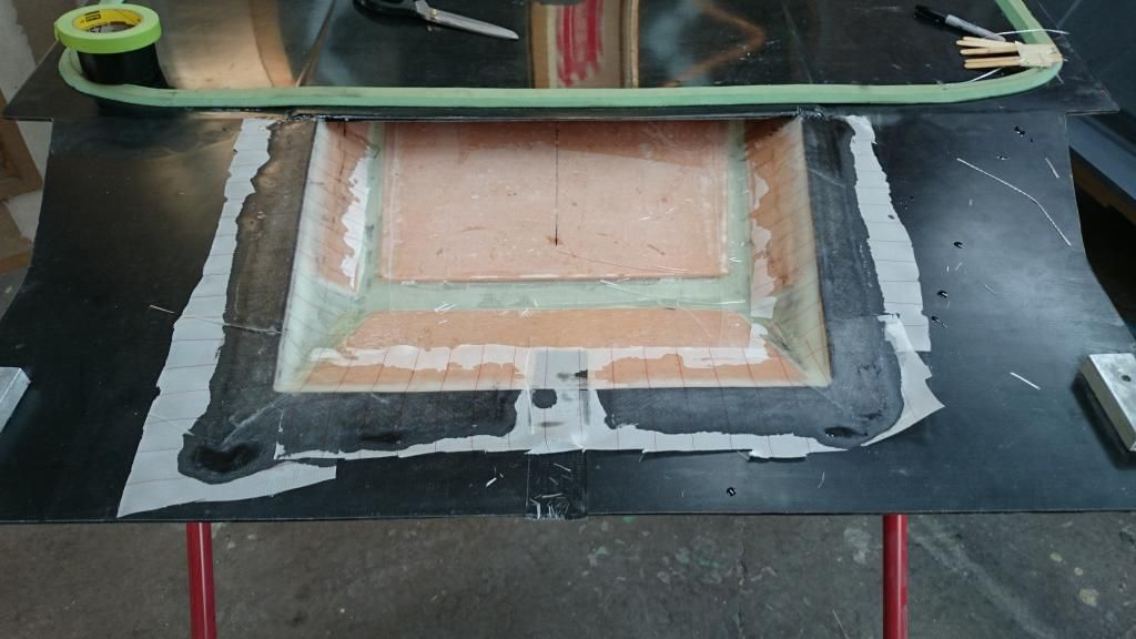
So the slow march toward getting it ready to paint continues. I laminated the vent onto the engine lid. Nothing too exciting to see:
Image

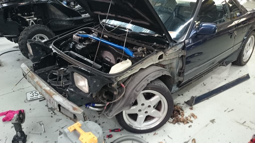
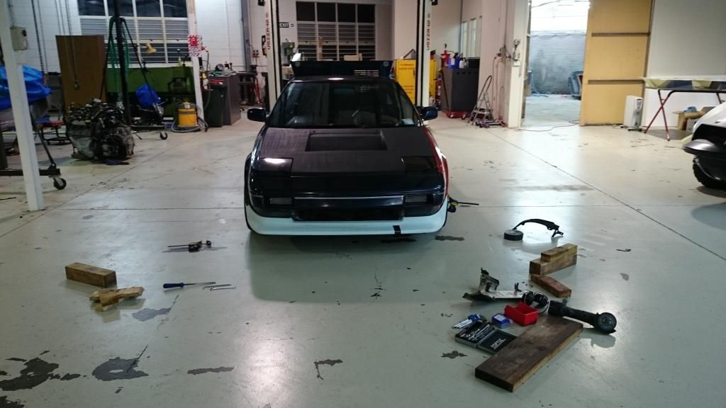
With the engine lid nearly complete, I turned my attention to the other bodywork that needs doing. I have replacements for both front guards as the old ones have minor dents that would be a pain to fix. So, off came some body panels:
Image

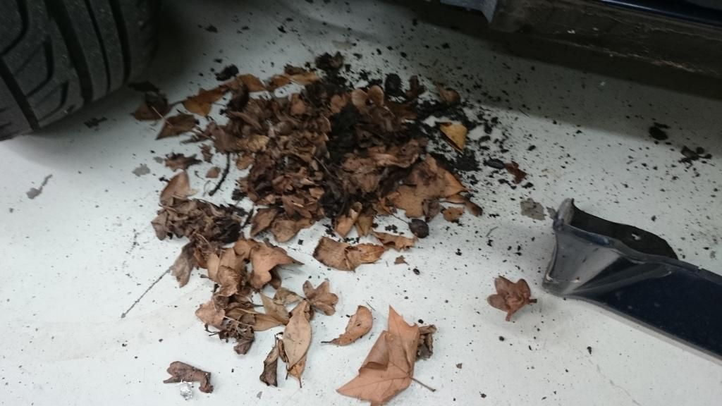
Out came some leaves
Image

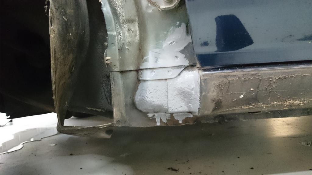
There was a patch of surface rust forming where the leaves had been sitting; fortunately it wasn't very deep and after a thorough wire-brushing I coated it in POR15
Image

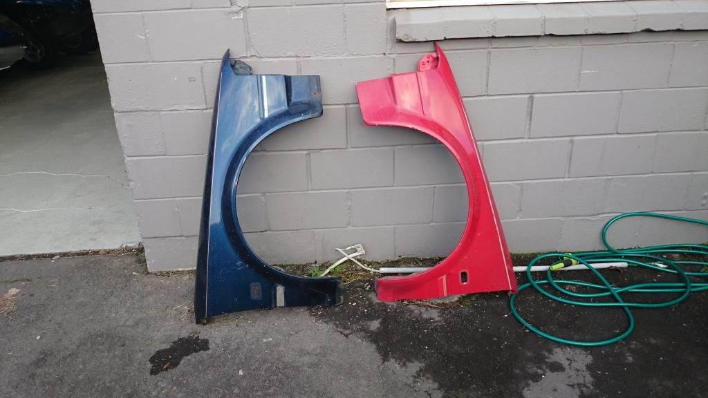
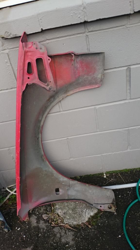
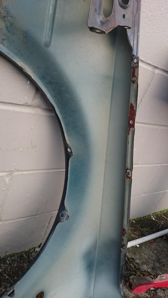
Replacement guards
Image

The front left (red) one is in pretty good nick. It has a couple of minor dents which I think should be easily knocked out.
Image

The front right (blue) one is very straight but has some rust on the underside. Nothing major but I'll need to clean it up and POR15 the inside before I put it on the car
Image

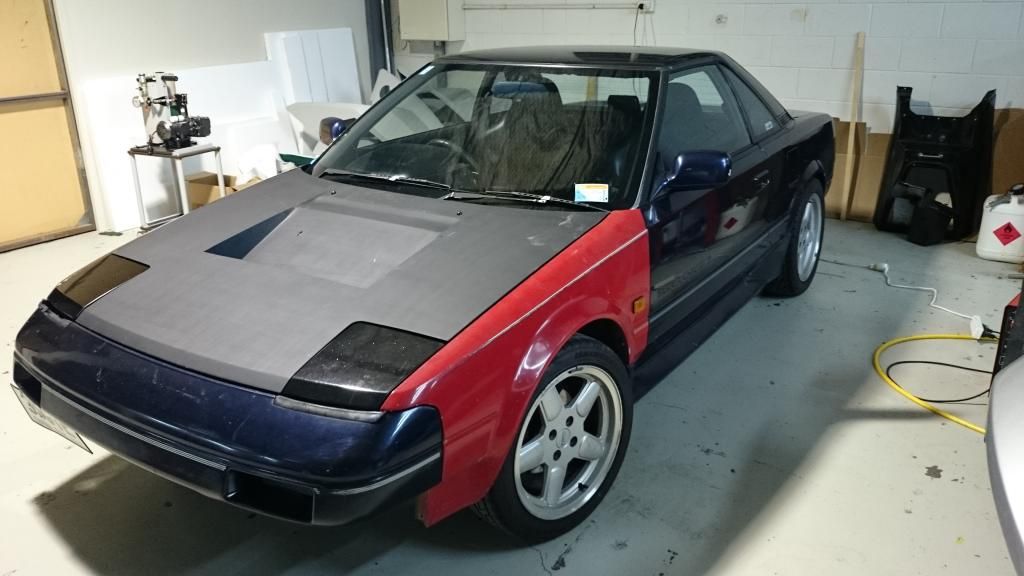
So now the car is blue, gloss black, matte black and red. Before it gets painted I think I'll be able to add white and grey to the list
Image

I'm also considering what to do about the radiator, which is leaking. The radiator is an SW20 one (which is nearly identical to the AW11) - replacement aluminium ones can be had for $250 which seems like a bargain. I may go for one of those but I'm also considering using an old test radiator from work - need to check out what we've got but the sizes are quite similar and it'll save me a few $$ :) I am also thinking about slightly changing the angle of the radiator - it's currently horizontal but if I lower the back edge down slightly and lift the front up slightly it'll improve the airflow path slightly and should slightly increase the effective cross section of the duct from the radiator to the bonnet. I'm mostly just wary of constantly revisiting and changing things I've already done - the cycle could continue forever!

As a final note on this update, the new stepper motor and driver configuration I've been testing is still giving me some grief. As with the last one it worked well bench testing it, but somehow going from the bench to the car has introduced some bugs. I haven't looked at it for a while so will have to check it out and see if there's any obvious problems, otherwise I'm thinking about either changing the speedo mechanism to an electronic one - if I can find something that will still fit into the AW11 cluster and fit properly behind the faceplate - or I might make one last try with a regular DC motor, using the speed output from the speedo to the ECU to create a feedback loop for controlling the motor speed.

User avatar
JasonFriday13
Club Member - MR2OCNZ
Posts: 2503
Joined: Mon May 21, 2007 5:19 pm
Stomping Ground: Taranaki
Prime Mover: SW20
First name: Jason

Re: Malcolm's 3SGTE AW11

Post by JasonFriday13 »

Malcolm wrote:So now the car is blue, gloss black, matte black and red. Before it gets painted I think I'll be able to add white and grey to the list.
:lol: :lol: :lol:

What about pink? :mrgreen:
Jason Ross, current cars:
Project: 1990 SW20 GT, 1992+ brake swap, 1992+ subframe swap, 1996 Celica turbo engine swap, 1996 MR2 LSD gearbox swap, Caldina Turbo coil-on-plug ignition, Link G4 Storm, 161kw @ 10psi.
Daily: 2004 Toyota Vitz RS, 1.5L, 5sp
Tow rig: 2009 Camry, 2.4L, auto
Scrapped: 1989 SW20 GT, 1992 SW20 G-Limited, ex EssDub car, donor, 1997 Toyota Tercel 3dr hatch, front crash, 1990 SW20, G-Limited, ex EssDub car, roll crashed, donor
Sold: 1987 AW11 Supercharged, 1991 SW20 G-Limited, ex EssDub car

User avatar
Malcolm
Club Member - MR2OCNZ
Posts: 638
Joined: Mon May 24, 2010 8:24 pm
Stomping Ground: Auckland
Prime Mover: AW11
First name: Malcolm

Re: Malcolm's 3SGTE AW11

Post by Malcolm »

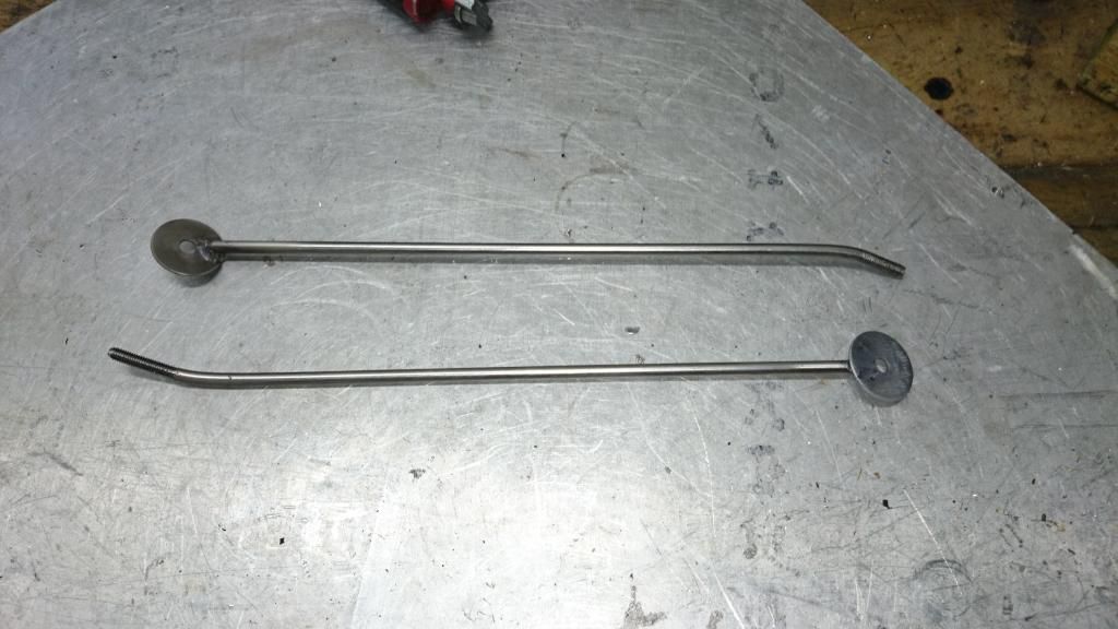
Got in to work early this morning so managed to get some stuff done. Nothing major but got the rust in the driver's side front guard tidied up and POR15'ed and made up some new stays for the front corners of the wheel arches.

ImageImage

I very briefly test fitted the Aerotech front lip. It seems like it may be about 20mm or so too wide
.. Will have a better look later but it won't be too big of a deal if I have to cut a section out of the middle; it would be surprising if this was the case though, I've never heard anyone have problems with that

User avatar
flying_wedge
Club Member - MR2OCNZ
Posts: 1696
Joined: Sat Aug 06, 2005 5:07 pm
Stomping Ground: Christchurch
Prime Mover: AW11
First name: Mark

Re: Malcolm's 3SGTE AW11

Post by flying_wedge »

Aerotech should be a good fit.
Maybe extend the stays to push the bottom end of the guards out to suit the aerotech?
Image

User avatar
Malcolm
Club Member - MR2OCNZ
Posts: 638
Joined: Mon May 24, 2010 8:24 pm
Stomping Ground: Auckland
Prime Mover: AW11
First name: Malcolm

Re: Malcolm's 3SGTE AW11

Post by Malcolm »

flying_wedge wrote:Aerotech should be a good fit.
Maybe extend the stays to push the bottom end of the guards out to suit the aerotech?
Yeah that's what I was thinking I might do. Need to get the rest of the parts on first and then a more careful test fit - if it's still too narrow then pushing the bottom corners of the guards out would probably be the best way to go

User avatar
Malcolm
Club Member - MR2OCNZ
Posts: 638
Joined: Mon May 24, 2010 8:24 pm
Stomping Ground: Auckland
Prime Mover: AW11
First name: Malcolm

Re: Malcolm's 3SGTE AW11

Post by Malcolm »

Quick update: this bodywork is taking ages...

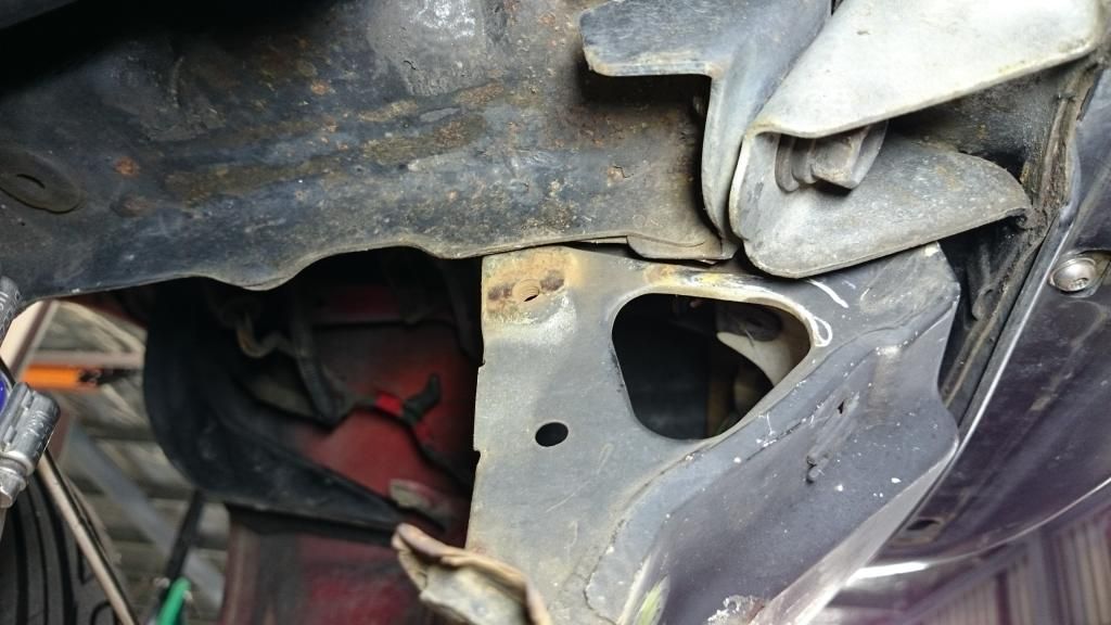
Because I've cut off the lower radiator support, I'm missing some of the mounting points for the front valance pieces:
Image

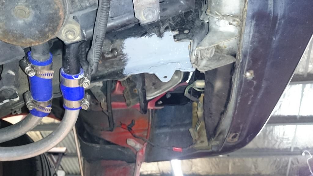
So I made up some little tags and welded them on, then coated them with POR15
Image

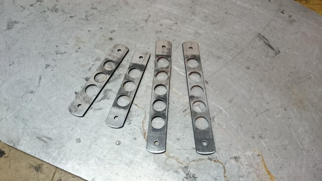
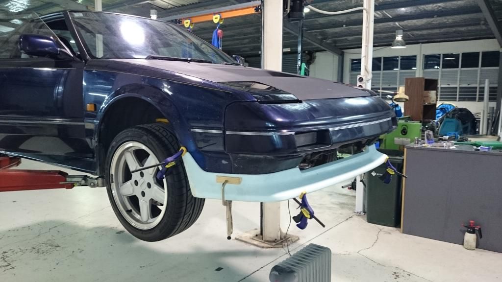
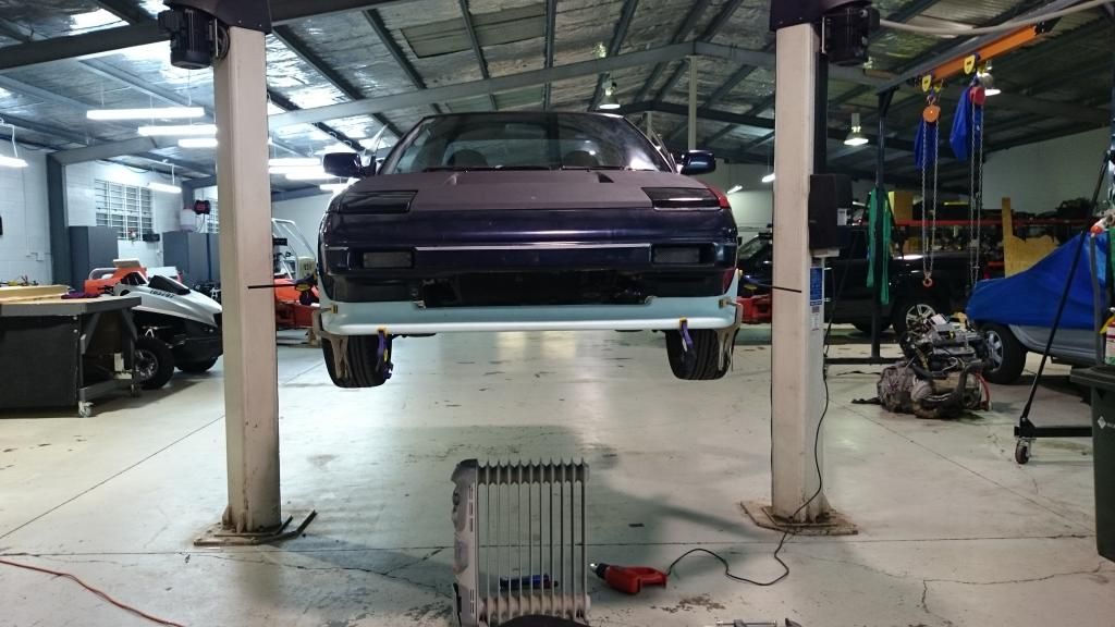
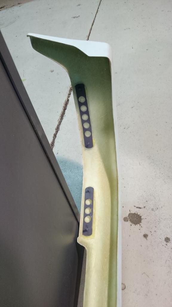
Also needed to figure out a good way to attach the Aerotech lip. I made these guys up:
Image

Then I glued them into place inside the lip
Image
Image
Image

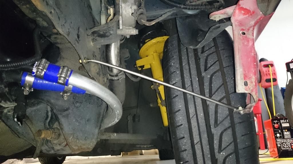
I ended up lengthening the rods from my previous post in order to push the corners of the guards out enough to suit the Aerotech lip.

I don't have any pictures yet, but I've actually begun painting! Nothing too exciting yet, just first coat of primer on the bonnet and engine lid, plus a few small pieces. I also borrowed a guard roller, and after fixing it I rolled the front guards. I'm off to Samoa for a week on Saturday so I'm hoping tomorrow to get a few more of the small pieces ready to paint. Maybe I will have it done before the end of the year?

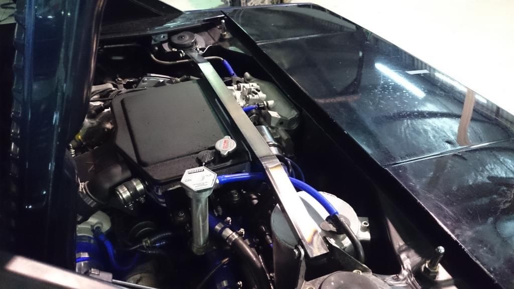
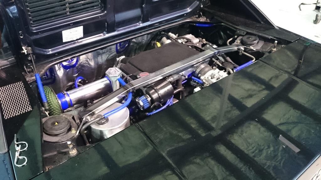
In other news I started on my rear strut brace a couple of weeks ago.
Image
Image

It's a very tight fit between the engine and the lid! I still need to add a few little details to it (mount for overflow etc) and then I'll get it powder coated. I might also get some parts away to be anodised at the same time (overflow, intake)

Image

User avatar
flying_wedge
Club Member - MR2OCNZ
Posts: 1696
Joined: Sat Aug 06, 2005 5:07 pm
Stomping Ground: Christchurch
Prime Mover: AW11
First name: Mark

Re: Malcolm's 3SGTE AW11

Post by flying_wedge »

Looking good Malcolm - good progress!
Sweet workshop space you have as well, and access to a hoist!

What glue did you use to stick those brackets to the lip? That seems the perfect solution and I have been wondering how to make this work for the lip to sit tighter to the body.
Image

Post Reply