I haven't quite decided on the colour yet... I have a fair idea but for now it's secret

I haven't done much more on the painting recently, but I have dropped the strut brace off for powder coating and the intake and overflow bottle for anodising. I've also turned my attention back to the speedo.
Despite the many hours of work I put in to the stepper motor drive for the speedo, it has just never been reliable. The reality is that the speeds I am asking the stepper to do are quite difficult for it, and the precision required in the alignment of the stepper shaft and the speedo input is too high for the mounting and drive methods I had used. Instead I've been looking to replace the mechanical speedo with an electronically driven one (like the late model SW20s).
First thing I needed to do was to find an electronic speedo that would fit with the least amount of modification possible. After about 3 hours at pick-a-part, dismantling speedos in at least 10 cars (if anyone goes to Avondale PAP and sees lots of dismantled instrument clusters floating around, you'll know why

), I had learned a lot about the variants of speedos that are common in Japanese cars and had found one which had the best combination of size, needle sweep degrees per km, odometer and trip meter positions and size, and trip meter reset lever location. It was surprising how many units seemed ideal but had one fundamental problem which meant they would either be very difficult to fit into the AW11 instrument cluster housing, or would not read the correct speed when behind the AW11 speedo faceplate (I can change this by altering the signal going in, but then the odometer won't be accurate).
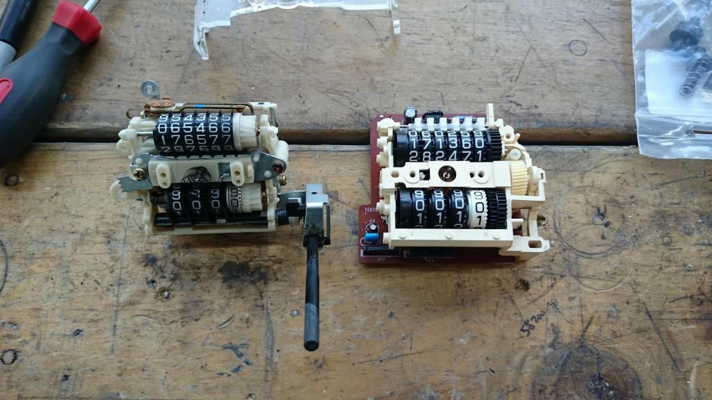
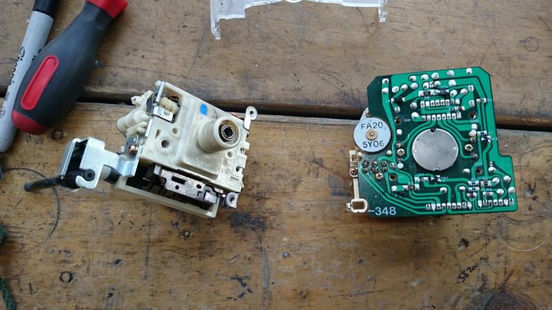
So in the end it was a Mazda Lantis that was nearest to ideal. Here are the units side by side
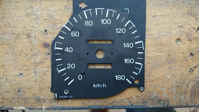
And here's the faceplate of the Mazda one laid on top of the AW11 one. The difference in windows for the odometer and trip meter is the main problem here
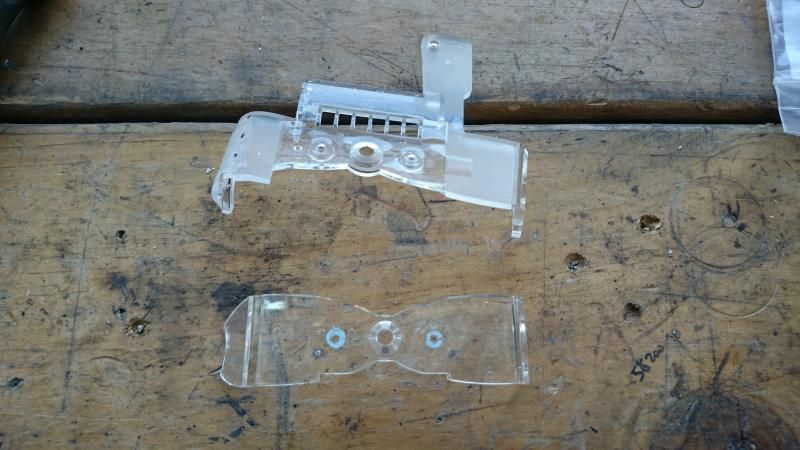
These are known as light pipes - the ends sit at the light source (the small bulbs in the back of the cluster) and light is internally reflected through it, emanating at the edges. These create the light that surrounds the odometer, trip meter and needle. The larger one is from the Mazda, I have trimmed it as well as heating it up and bending one corner to make it fit - unfortunately this bend created a lot of bubbles in the plastic which I suspect will reduce the effectiveness...we'll see
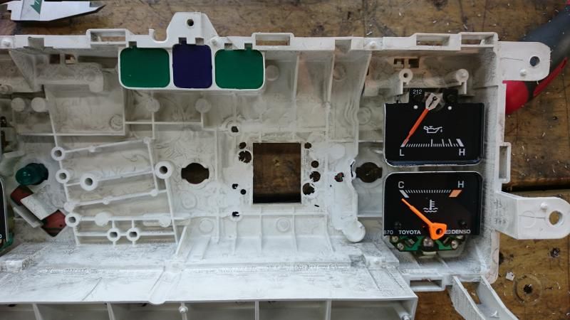
This shows (poorly) the modifications made inside the housing to fit the Mazda speedo. It's not obvious but I've used a die grinder to cut away all the reinforcing ribs that sit under the speedo, and I have also drilled some holes for where pins on the back of the Mazda speed sit deeper than the available depth - plus 3 holes which are dual purpose mounting and electrical feeds to the speedo
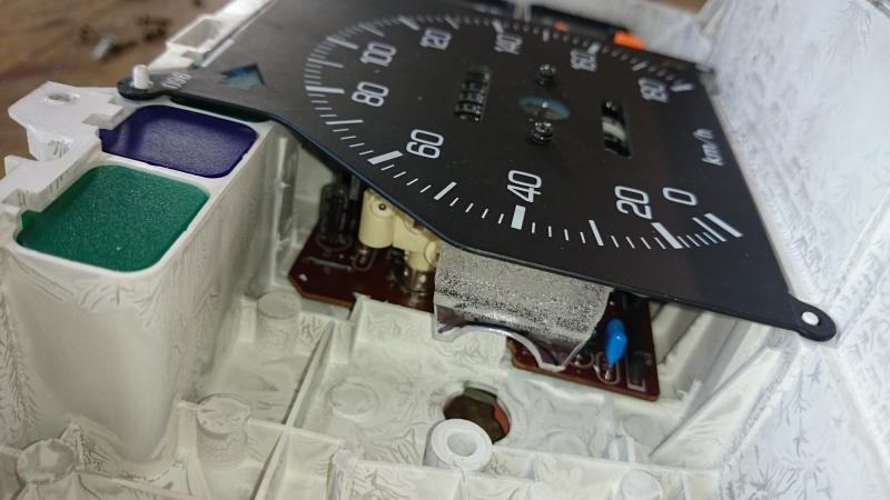
This shows how tightly the Mazda speedo fits. It really couldn't be bigger in any dimension and still fit without needing much more significant chopping
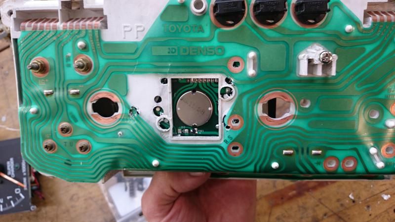
And here it is from the back. As you can see I was a bit of a muppet and managed to drill through the copper tracks on the cluster circuit once when I thought I was going to miss it, and also slipped and cut some with a knife as I was shaping the plastic! Repairable, but a pain. I did quite intentionally drill through the pad just above the letters "R.S.". As it turns out, this is usually the speed signal OUTPUT from the speedo to the ECU, but it aligns perfectly with the signal bolt hole for speed INPUT into the Mazda speedo, so I can feed a speed signal into the speed signal wire running to the ECU and it will also come to the dash and drive the speedo
The final stumbling block - the trip meter reset lever sat about 5mm lower and further to the right than the hole in the AW11 faceplate - so I cut the end of it off, fortunately part of it still runs directly below the hole so I should just be able to glue a rod on here and be done with it
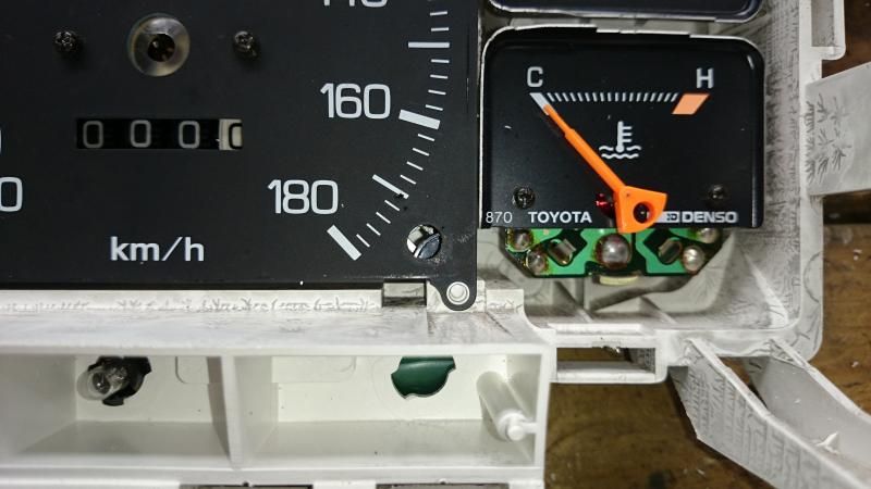
After spending an hour or so carefully trimming the windows for the odo and trip meter with a hot knife, here's how it's looking
Aside from tidying a few bits up, sticking on the odo reset lever and finding some suitable screws to hold the unit in, all that remains is the electronic side of things. I plan to continue using the Arduino and the speed sensor I had already installed, and have had the Arduino happily running the speedo on the bench so it should only be an hour's work or so to modify the software to do what I want it to.
Going through this process has uncovered some interesting possibilities if I can find an affordable way to make replacement gauge faces. I think I will follow that up later once this is finished and working


